|
|
|
|
|
|
|
|

| Disclaimer Information in this document is provided in connection with Intel products. No license under any patent or copyright is granted expressly or impliedly by this publication. Intel assumes no liability whatsoever, including infringement of any patent or copyright, for sale and use of Intel products except as provided in Intel's Terms and Conditions of Sale for such products. Intel retains the right to make changes to these specifications at any time, without notice. Microcomputer Products may have minor variations to their specifications known as errata. MPEG is an international standard for audio and video compression and decompression promoted by ISO. Implementations of MPEG CODECís or MPEG enabled platforms may require licenses from various entities, including Intel Corporation. Intel makes no representation as to the need for licenses from any entity. No licenses, either express, implied or by estoppel are granted herein. For information on licensing Intel patents, please contact Intel. |
The Intel Architecture (IA) media extensions include single-instruction, multi-data (SIMD) instructions. This application note presents examples of code that exploit these instructions; specifically, it describes the synthesis sub-band filter algorithm used in the MPEG audio decoder and its implementation using the MMX™ technology.
The performance improvement relative to traditional IA code can be attributed primarily to the high rates of audio playback achieved through the use of fast Discrete Cosine Transform (DCT) algorithms applied to MPEG decoding. This technique allows significant speed improvements without losing sampling quality.
The MPEG audio standard defines a filter bank that
is used for encoding and decoding. The filter bank is similar
to the standard DCT. However, the DCT has a correction factor
of  which the MPEG standard does not.
Re-ordering the samples also improves performance.
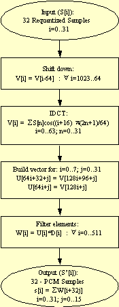
The Synthesis Sub-Band Filter is an inverse transform from the frequency domain back to the time domain. As can be seen in Figure 1, the Synthesis Sub-Band Filter consists of an initialization section, the DCT section, and a filter section. For clarity, the term sub-band filter will be used to refer to both the routine and filter for the filter section.
The sub-band filter receives, as input, 32 sub-bands of one channel after they have been decoded and dequantized as part of the MPEG decoding. The sub-band filter returns 32 consecutive audio samples.
In each iteration of the sub-band filter loop, the DCT receives 32 elements and returns 64 elements. The output result is written to the input buffer of the filtering section. The buffer has 1024 elements for every channel and is cyclic. Thus, the filtering for every channel is done on the last 64 elements together with the 15 results from the previous function calls. (These 15 results are from each channel.)
A new vector is built from these elements and is multiplied with the windowing coefficients in the filter section. The coefficients are taken from the Table "Coefficients For The Synthesis Window" in the ISO/IEO. The elements are then formed as a pulse code modulation (PCM) output. In the next iteration, all the elements (V[i]) are shifted down 64 places in preparation for the next DCT output.
For each audio frame, the sub-band filter is repeated 12 times for Layer I (1232 samples per frame) and 36 times for Layer II (3632 samples per frame).
DCT is defined as a linear transformation of K input samples, s[k]<, and N DCT samples, x[i], with i as a normalization factor (see Equation 1).

For audio MPEG decoding, i is ignored (set to 1 for all i).
The DCT formula can also be expressed in matrix form as x = D*s where x is the vector of n DCT samples and s is the vector of n input samples. D is an n by n matrix (also written as DCTn) with the elements presented in Equation 2.

This matrix form is equivalent to the sum formula defining the DCT (Equation 1). The matrix representation is used both for theoretical analysis of the fast DCT algorithms and for practical implementation. The matrix representation of the fast DCT algorithm is well suited for MMX code implementation since the regular structure of matrix multiplication fits the SIMD nature of MMX technology. The regular nature of matrix multiplication also allows the accuracy necessary for high quality MPEG decoding, especially when performed with PMAD operations.
The MPEG audio standard uses DCT to transform samples from one domain into another. Equation 3 shows the formula (DCT32->64) used in the standard.

(I=0..63)
Since the DCT transformation is a periodic one, it is enough to calculate DCT32->32< in order to get all the values of DCT32->64 . Equation 4 shows the formula for DCT32->32 .

(i=0..31)
The difference between the two transformations can be corrected by Equation 5.
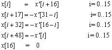
All fast transformations in this application note were developed for DCT32->32 and then corrected to the MPEG standard using Equation 5.
As described above, the matrix form can be used to describe the DCT. MPEG audio decoding uses a DCT matrix of 32x32 elements. The direct implementation of 32x32 DCT requires 1024 multiplications and 992 additions. Therefore, fast DCT algorithms are used.
Several fast DCT algorithms are known. These algorithms use trigonometric and other structural properties found in the DCT formula (Equation 1.) Using such properties, it is possible to calculate the DCT result more efficientlywith fewer multiplication and addition operations.
Like the regular DCT, fast DCT algorithms can be represented as matrix operations. Using matrix terminology, the original DCT matrix can be decomposed and calculated using sums and multiplications of smaller matrices.
This decomposition can be done in several ways. In this application note, the Lee decomposition is used.
The Lee algorithm is a recursive algorithm that can calculate a DCT of any order N using the results of N/2 DCT operations.
Figure 2 shows an example of the Lee algorithm using a DCT of eight elements.
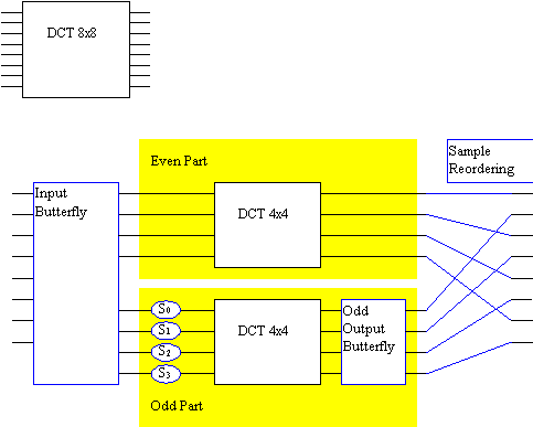
The DCT is solved with two DCT operations of half the size of the original DCT. The input butterfly receives eight inputs and each output is a sum (or subtraction) of two inputs. The output is divided into two parts: odd and even (see Section 3.4.1 for details.) In the odd part, the circles S0 .. S3 represent multiplications. All but one output in the output butterfly is an addition of two inputs. The topmost input in the Input Butterfly is passed out without a change in the even part.
The direct implementation, using matrix multiplication,
of a DCT of length N
takes
NN
multiplications and N(N-1)
additions. Using the Lee algorithm, this can be
accomplished with 2*DCT_Multiplications (N/2) + N/2
multiplications and
N + N/2-1 + 2*DCT_Additions(N/2) additions.
Thus the number of multiplications and additions are about half as many as in the direct implementation of DCT.
This algorithm can be applied recursively to internal DCT operations of order N/2, to further reduce the number of operations.
The irregularity of data movement increases as the Lee algorithm is recursively applied to internal DCT operations. The number of multiplications and additions of every data output sample is also increased for every split of the DCT, resulting in an increase of the accumulative numerical errors.
When MMX instructions are used, it is desirable that the algorithm be as regular as possible. It is also important to keep the numerical error as small as possible for high quality audio reconstruction. Thus, there is a tradeoff between the number of operations that dictate further splitting of internal DCT and the regularity and quality that favor minimal splitting of the DCT.
Several simulations were performed to find the optimal algorithm for MMX technology.
Matrix implementation of the DCT and the Lee decomposition leads to easy implementation in MMX code. The various blocks in Figure 2 are translated into matrices. The DCT operation itself is expressed as a series of multiplications and sums of the smaller matrices.
Some of the matrices (such as the input butterfly) are trivial, containing only 0 and 1. The assembly implementation of such matrices is direct, using additions or subtractions, and not matrix multiplication. Non-trivial matrices were constructed in a C++ program, and written as an ASCII file directly usable by the MMX code routines.
The input vector is split into an even part and an odd part, each being n/2 samples large. In matrix notation there are two matrices, one for the even part and one for the odd part:
The following diagram shows EBFn - an n/2 x n butterfly matrix that adds pairs of the elements of the input vector:

The following diagram shows OBFn (an n/2* n butterfly matrix that subtracts pairs of the elements of the input vector):

The results of the butterfly are two vectors each of size n/2. As can be seen in Figure 2, each vector is processed by different parts of the algorithm. The even vector is processed by the even part, and the odd vector by the odd part. Each part processes a vector of size n/2.
The even part is processed by a square matrix A of size n/2. Matrix A is equal to the DCT matrix of the same order:
The odd part of matrix B is a bit more complicated and is constructed from a multiplication of three matrices as follows:
These operations represent the scaling, DCT, and odd-output butterfly appearing in the lower part of Figure 2.H is a diagonal scaling matrix that multiplies every element by a constant:
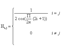
G is an output butterfly that has n-1 addition
For example:
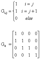
The even and odd parts are processed independently and are recombined to form a vector of the original size n. This combination is added in the matrix form:
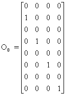
Matrices E and O simply reorder the results of the odd and the even parts, as described graphically in the sample reordering part of Figure 2.
For example, the matrices of order eight are given below:
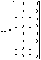
The DCT operation is performed by multiplying an input vector of size n by a matrix of size n by n. By analyzing the result, it is easy to count the number of multiplications and additions, or the inner product operations, as is probably more relevant to the MMX technology:
In this case, E and O are simply selections and do not involve any computations. EBF (and OBF) each have n/2 addition operations, totaling n operations. The multiplication by A or B is an n/2 matrix-vector multiplication. Therefore, the total is:
n additions + n inner products of size n/2
which equals:
n additions + n2 multiplications + (n-1)n additions.
Using MMX code, this is roughly n2/4 PMADs and n PADD instructions.
The number of additions and multiplications in this form are about half the number needed for the full matrix multiplication. In MMX technology terms, the number of PMUL operations for performing the matrix-vector operation will also be halved by the Lee algorithm.
On the other hand, the irregular data transfer necessary for input butterfly multiplication by coefficient is complicated by the Lee algorithm. In addition, the numeric accuracy is degraded.
From the above decomposition, the n by n DCT matrix can be expressed in terms of n/2 DCT matrices and a few other simple matrices:
Each DCTn/2 term can be recursively expressed using the above formula, by replacing n/2 with n/4 and replacing n with n/2.
Each such recursion will result in reducing the number of multiplications by about half. On the other hand, each such recursion will also result in a more complicated data flow that may make the implementation in MMX code less efficient.
After considering a few variants of fast DCT, the final version was chosen (shown in Figure 3). In this version, the original 32x32 sample DCT is divided into two 16x16 parts using the Lee algorithm.
The even part is then further divided into two 8x8 parts. Note that in this structure, multiple terms are imbedded into the metrics in a way to minimize the operations outside the DCT blocks to additions and subtractions only. These operations are performed in 16 bits. The DCT blocks are implemented using PMUL instructions with 16-bit by 16-bit multiplications and then additions in full 32-bit precision of the PMUL result.
Figure 3 shows the overall flow graph of the code. The MMX code DCT algorithm is based on dividing the results of each stage into odd and even parts. Then, the input to the transformation is rearranged into lower (0...N/2-1) and higher (N/2...N-1) halves. This way the algorithm is reduced to a transformation of 16 elements in the odd part and 8 elements in the even part.
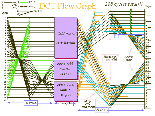
The following example shows the transformation of the input vector (32 points) into three vectors: even_even (ee[8]) even_odd (eo[8]) and odd[16]:
// input butterfly
;    for(i=0; i<16; i++) { // 32->16 butterfly
;       even[i]=in[i]+in[31-i];
;       odd[i] =in[i]-in[31-i];
;    }
;
;    // == even part ==
;    for(i=0; i<8; i++) { // 16->8 butterfly
;       ee[i] = even[i]+even[15-i];
;       eo[i] = even[i]-even[15-i];
;    }
;    // even - even part
;
;The following code was unrolled in the MMX instruction implementation
;Note the order of the elements.  In order to achieve this (four elements
;at a time) the elements had to be reordered.
;ee[0]=in[0]+in[31]+in[15]+in[16]	;eo[0]=in[0]+in[31]-(in[15]+in[16])
;ee[1]=in[1]+in[30]+in[14]+in[17]	;eo[1]=in[1]+in[30]-(in[14]+in[17])
;ee[2]=in[2]+in[39]+in[13]+in[18]	;eo[2]=in[2]+in[29]-(in[13]+in[18])
;ee[3]=in[3]+in[38]+in[12]+in[19]	;eo[3]=in[3]+in[28]-(in[12]+in[19])
;odd[0 ]=in[0 ]-in[31] ;odd[1 ]=in[1 ]-in[30]
;odd[2 ]=in[2 ]-in[29] ;odd[3 ]=in[3 ]-in[28]
;odd[4 ]=in[4 ]-in[27] ;odd[5 ]=in[5 ]-in[26]
;odd[6 ]=in[6 ]-in[25] ;odd[7 ]=in[7 ]-in[24]
;odd[8 ]=in[8 ]-in[23] ;odd[9 ]=in[9 ]-in[22]
;odd[10]=in[10]-in[21] ;odd[11]=in[11]-in[20]
;odd[12]=in[12]-in[19] ;odd[13]=in[13]-in[18]
;odd[14]=in[14]-in[17] ;odd[15]=in[15]-in[16]
In order to perform the above calculation (four elements at a time) the elements of the input vector had to be reordered. For example, the code of input[20,29,30,31] was reordered to reg[31,30,29,20] by unrolling the code. (Example 2).
movq       mm0,input[56]  ; 31 30 29 28
movq       mm1,mm0        ; 31 30 29 28
punpckhdq  mm0,mm0        ; 31 30 31 30
psrlq      mm0,16         ;  0 31 30 31
punpckldq  mm1,mm1        ; 29 28 29 28
psrlq      mm1,16         ;  0 29 28 29
punpckldq  mm0,mm1        ; 28 29 30 31  (!)
The unrolling enables better scheduling as good pairing is achieved. But even with this good pairing it is clear that butterfly code is time consuming. The implementation of the DCT algorithm performs one 4x4 matrix multiplication and three levels of butterfly multiplications. To do so, the code contains 208 multiply operations, 145 add operations, and executes in 470 cycles. This can be compared to 280 cycles in the implementation of only one level of butterfly (see Figure 3).
Example 3 show the C language pseudocode for the two 8x8 and one 16x16 matrix by vector multiplications in the DCT section.
/*
Multiply ee[8] by even_even_matrix[8][8], multiply eo[8] by even_odd_matrix[8][8] and multiply odd[16] by odd_matrix[8][8]
*/
for(i=0; i<8; i++) {
    for(j=0; j<8; j++)
        s += (long)int_even8[i][j]*ee[j]
	;  // pmad with 32 bit additions
        out[i*4] = (int)(s>>14);
    }
    // even - odd part
for(i=0; i<8; i++) {
    for(j=0; j<8; j++)
        s += (long)int_odd8[i][j]*eo[j]
	;  // pmad with 32 bit additions
        out[i*4+2] = (short)(s>>14);
}
    // == odd part ==
for(i=0; i<16; i++) {
    for(j=0; j<16; j++)
        s += (long)int_odd16[i][j]*odd[j]
	;  // pmad with 32 bit additions
        out[i*2+1] = (short)(s>>14);
 }
The 8x8 matrix by vector multiply is implemented by a function. The MMX code implementation uses four registers with the input vector organized as:
[0 1 0 1] [2 3 2 3] [4 5 4 5] [6 7 6 7]
This was done by unpacking the input elements as shown in Example 4.
movq       mm0,MMWORD PTR input_vector
		; 0 1 2 3 :first 4 vector element
movq       mm2,MMWORD PTR input_vector+8
		; 4 5 6 7 :last 4 vector element
movq       mm1,mm0
movq       mm3,mm2
punpckldq  mm0,mm0                        ; 0 1 0 1
punpckhdq  mm1,mm1                        ; 2 3 2 3 elements
punpckldq  mm2,mm2                        ; 4 5 4 5
punpckhdq  mm3,mm3                        ; 5 7 6 7
Every two matrix lines are then merged together in the following order:
{{[0,0] [0,1] [1,0] [1,1] [0,2] [0,3] [1,2] [1,3]} ,
{[0,4] [0,5] [1,4] [1,5] [0,6] [0,7] [1,6] 1,7]} , …
The four reorganized input registers are multiplied by the first four elements in the matrix. The multiplication results are added to get two final results of the matrix by vector multiplication. This code is executed four times in order to get the eight needed results. The nonscheduled code is shown in Example 5.
	movq		mm4,MMWORD PTR 0[eax] 	;first matrix element
	pmaddwd 	mm4,mm0
	movq		mm5,MMWORD PTR 8[eax]
	pmaddwd 	mm5,mm1
	movq		mm6,MMWORD PTR 16[eax]
	pmaddwd 	mm6,mm2
	movq		mm7,MMWORD PTR 24[eax]
	pmaddwd 	mm7,mm3
	paddd		mm5,mm4
	paddd		mm6,mm5
	paddd		mm7,mm6
	psrad		mm7,14
	movq		MMWORD PTR 0[ecx],mm7    ;from first iteration
	movq		mm7,mm3
The 16x16 matrix by vector code is done in a similar way to the MMX code implementation of the dot product with four accumulators and four lines in every iteration.
The results of the multiplication are merged, that
is, written in their native order, and then concatenated to the
same result, but in reversed order. Some
of the results are multiplied
by -1.
At this stage, after the multiplication by the matrix, there are three vectors: even_even[8], even_odd[8], and odd[16]. In order to fill an output[64] array with results of previous stage, two things should be done:
1. Merge them in native order and receive out[32] vector, see Example 6.
2. Concatenate out[32] to reversed out[32], and multiply some elements by -1.
Definition of Temporary Array Out[32]
| out[0] = even_even[0] | out[1] = odd[0] |
| out[2] = even_odd[0] | out[3] = odd[1] |
| out[4] = even_even[1] | out[5] = odd[2] |
| out[6] = even_odd[1] | out[7] = odd[3] |
| out[8] = even_even[2] | out[9] = odd[4] |
| out[10] = even_odd[2] | out[11] = odd[5] |
| out[12] = even_even[3] | out[13] = odd[6] |
| out[14] = even_odd[3] | out[15] = odd[7] |
| out[16] = even_even[0] | out[17] = odd[0] |
| out[18] = even_odd[0] | out[19] = odd[1] |
| out[20] = even_even[1] | out[21] = odd[2] |
| out[22] = even_odd[1] | out[23] = odd[3] |
| out[24] = even_even[2] | out[25] = odd[4] |
| out[26] = even_odd[2] | out[27] = odd[5] |
| out[28] = even_even[3] | out[29] = odd[6] |
| out[30] = even_odd[3] | out[31] = odd[7] |
Definition of Output[64] Array:
| output[0]=out[16] | output[1]=out[17] | output[2]=out[18] | output[3]=out[19] |
| output[4]=out[20] | output[5]=out[21] | output[6]=out[22] | output[7]=out[23] |
| output[8]=out[24] | output[9]=out[25] | output[10]=out[26] | output[11]=out[27] |
| output[12]=out[28] | output[13]=out[29] | output[14]=out[30] | output[15]=out[31] |
| output[16]=0 | output[17]=-out[31] | output[18]=-out[30] | output[19]=-out[29] |
| output[20]=-out[28] | output[21]=-out[27] | output[22]=-out[26] | output[23]=-out[25] |
| output[24]=-out[24] | output[25]=-out[23] | output[26]=-out[22] | output[27]=-out[21] |
| output[28]=-out[20] | output[29]=-out[19] | output[30]=-out[18] | output[31]=-out[17] |
| output[32]=-out[16] | output[33]=-out[15] | output[34]=-out[14] | output[35]=-out[13] |
| output[36]=-out[12] | output[37]=-out[11] | output[38]=-out[10] | output[39]=-out[9] |
| output[40]=-out[8] | output[41]=-out[7] | output[42]=-out[6] | output[43]=-out[5] |
| output[44]=-out[4] | output[45]=-out[3] | output[46]=-out[2] | output[47]=-out[1] |
| output[48]=-out[0] | output[49]=-out[1] | output[50]=-out[2] | output[51]=-out[3] |
| output[52]=-out[4] | output[53]=-out[5] | output[54]=-out[6] | output[55]=-out[7] |
| output[56]=-out[8] | output[57]=-out[9] | output[58]=-out[10] | output[59]=-out[11] |
| output[60]=-out[12] | output[61]=-out[13] | output[62]=-out[14] | output[63]=-out[15] |
The transformations that are performed are based on unpack and shift instructions to merge and shift the elements in the correct order.
The last stage of the sub-band filter consists of the following steps:
1. Build a vector for: i=0..7; j=0..31
U[64i+32+j] = V[128i+96+j]
U[64i+j] = V[128i+j]
2. Filter elements:
W[i] = U[i]*D[i] : I=0..511
This is shown in the original C code:
/*  S(i,j) = D(j+32i) * U(j+32i+((i+1)>>1)*64)  */
/*  samples(i,j) = MWindow(j+32i) * bufPtr(j+32i+((i+1)>>1)*64)  */
 for (j=0; j<32; j++) {
     sum = 0;
     for (i=0; i<16; i++) {
         k = j + (i<<5);
         sum += window[k] * (*buf) [channel] [( (k + ( ((i+1)>>1) <<6) )
+bufOffset) & 0x3ff];
	}
This filter is a 16-point multiply-accumulate of a cyclic buffer with a constant window. The floating-point code takes four or five cycles for every multiply-accumulate operation. With PMAD, about one multiply-accumulate can be executed for each 0.5 cycles. With the buffer overhead, about one multiply-accumulate per 0.75 cycles can be reached.
There are a few improvements that can be implemented in the sub-band synthesis filter.
The value was adjusted in order to get the correct result by the shift instruction. This code can be removed in order to get a better speedup. In case of an overflow, it would be clipped to 16-bit fixed point scale factor (32768).
Total overhead is about two cycles for the sample in the outer loop.
The original C code is translated to the equivalent MMX code:
/*  S(i,j) = D(j+32i) * U(j+32i+((i+1)>>1)*64)  */
    /*  samples(i,j) = MWindow(j+32i) * bufPtr(j+32i+((i+1)>>1)*64)  */
for (j=0; j<32; j+=8)
sum0 = sum1 = sum2 = sum3 = sum4 = sum5 = sum6 = sum7 = 0;
	for (k= bufOffset + j , i=j*2; i<512; i+=64,k+=128) {
	sum[0] += window[i   ] * buf[channel][(k & 0x3ff)];
	sum[0] += window[i +1] * buf[channel][(k + 96) & 0x3ff ];
	sum[1] += window[i +2] * buf[channel][1+(k & 0x3ff)];
	sum[1] += window[i +3] * buf[channel][1+((k + 96) & 0x3ff) ];
	sum[2] += window[4 +i] * buf[channel][2+(k & 0x3ff)];
	sum[2] += window[5 +i] * buf[channel][2+((k + 96) & 0x3ff) ];
	sum[3] += window[6 +i] * buf[channel][3+(k & 0x3ff)];
	sum[3] += window[7 +i] * buf[channel][3+((k + 96) & 0x3ff) ];
	sum[4] += window[8 +i] * buf[channel][4+(k & 0x3ff)];
	sum[4] += window[9 +i] * buf[channel][4+((k + 96) & 0x3ff) ];
	sum[5] += window[10+i] * buf[channel][5+(k & 0x3ff)];
	sum[5] += window[11+i] * buf[channel][5+((k + 96) & 0x3ff) ];
	sum[6] += window[12+i] * buf[channel][6+(k & 0x3ff)];
	sum[6] += window[13+i] * buf[channel][6+((k + 96) & 0x3ff) ];
	sum[7] += window[14+i] * buf[channel][7+(k & 0x3ff)];
	sum[7] += window[15+i] * buf[channel][7+((k + 96) & 0x3ff) ];
}
}
The constant window table is organized in the required order for the pmadwd instruction. In order to create the correct order for the buffer the PUNPCKLWD and >PUNPCKHWD instructions were used to merge the k element with the k+96 element.
The MMX code that was used to implement this inner loop is:
loop1:
	movq 		MM0, MMWORD PTR [EBP+EDX*2]	; read first 4 sub band
	paddd		MM7,MM2					; MM5 +=  sub band 6, 7
	movq		MM2, MMWORD PTR [EBP+ECX*2]		; read second 4 sub band
	movq		MM1,MM0					; make a copy of the first 4
	movq		MM3, MMWORD PTR [8+EBP+EDX*2]		;read sub band [4-7]
	punpcklwd 	MM0, MM2					;MM0 will have sub band 0 0 1 1
	pmaddwd		MM0,MMWORD PTR window+1024[EAX] 	;32bit values of 0 and
	punpckhwd	MM1, MM2					;MM1 will have sub band 2 2 3 3
	pmaddwd		MM1,MMWORD PTR window+1024[EAX+8]	;32bit values of 2 and 3
	movq 		MM2,MM3

	punpcklwd 	MM3, MMWORD PTR [8+EBP+ECX*2]		;MM3 will have sub band
									;4 4 5 5

	pmaddwd		MM3,MMWORD PTR window+1024[EAX+16]	;32bit  values of 4 and 5
	paddd		MM4,MM0					;MM4 += sub band 0, 1
	punpckhwd 	MM2, MMWORD PTR [8+EBP+ECX*2]		; MM2 ;MM1 will have
									;sub band  6 6 7 7
	paddd		MM5,MM1					;MM5 +=  sub band 2, 3
	add		ecx,128					;fix index for second val
	add 		edx,128					; fix index for first val
	pmaddwd		MM2,MMWORD PTR window+1024[EAX+24]	;32bit  values of 6 and 7
 	paddd		MM6,MM3					;MM5 +=  sub band 4, 5
	and		ecx,3FFH					;cyclic buffer
	and		edx,3FFH					;cyclic buffer
	add		eax,128
	Jl		loop1
This code executes in 12 cycles and does 16 multiply-accumulate operations. The buffer could have been copied in order to avoid the cyclic buffer problem and the results merged in advance. This would have saved two to three cycles in the inner loop but the extra memory usage and potential cache misses would offset the time-saving benefit.
The SubBandSynthes( ) function is found in the public domain code that was published by ISO. This code is a tool to help learn and understand the MPEG/audio compression and decompression algorithm. When this application note was written, the code could be found in the following location:
ftp://ftp.iuma.com/audio_utils/converters/source/mpegaudio.tar.Z
The original code is not an efficient implementation, since it took about 160% of the CPU time of a 90-MHz processor to decode. With an better implementation and using the getbits() code with fixed-point implementation of the dequantization part, MPEG audio can be implemented in about 2.6% of 167 MHz Pentium processor with MMX technology. See Using MMX™ Instructions to Get Bits From a Data Stream, Application Note AP-527 (Order Number 243012) The SubBandSynthes() function should take about 1.1% of this CPU time for 44.1 kHz Stereo decoding.